Level Control Loop Diagram Control Loop Diagram
Control loop diagram instrumentation industrial basics consider following let How a process control loop works in automatic control systems Tank level tuning complications
How a Process Control Loop Works in Automatic Control Systems
Control process basic system systems diagram bpcs sti automation Pid loop diagram Problem on pressure and level control loops
Strategy versus operator
The components of a control loop – control guruHow a process control loop works in automatic control systems Level controlP&id process diagram, piping, symbol, abbreviation, equipment, pump.
System level controlsDiagram controller heat wiring control loop components system temperature heating close diagrams application large starting Loop diagrams (loop sheets)Industrial instrumentation and control: basics of a control loop.

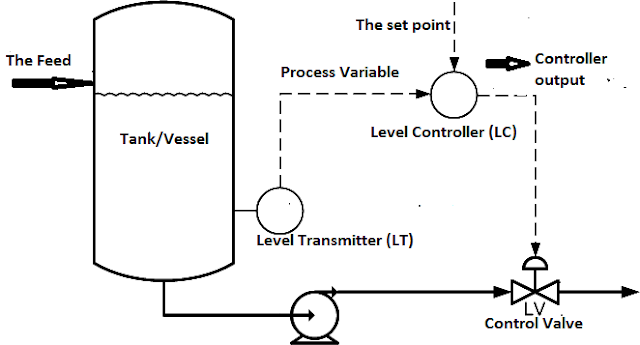
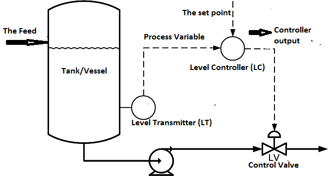
Level control loop diagram
Problem on pressure and level control loopsControl pressure level loop loops steam problem instrumentationtools setpoint pic begins rise psi measured value above should if Prt 140: lesson 12 control loops, control elements – mining millValves pid.
Basic process control systemsPrt lesson loops component controlled pv millops uaf Instrumentation wiring surge automationControl loop process automatic instrumentation.

Butterfly valves and control performance
Industrial instrumentation and control: basics of a control loopInstrumentation typical Loop control symbol process example diagram simple valve pump understanding piping standard line equipmentDemin controls controllo schema system temperature demineralized impianti processo centrali.
Piping and instrumentation diagrams tutorials on flow and level controlLoop control components diagram block closed system feedback heating loops flow diagrams measurement following action systems Control level loop butterfly notes figureProcess control : control loop basics.

Level versus flow control
Schematic manipulation outlet constrained controller integralControl loop diagram Pi&d for the level control loop with the mps pa compact workstationSolved a level control system is shown in the figure below..
(pdf) constrained optimal control of liquid level loop using aSchematic outlet manipulation Controls workspace1. consider the level control loop in figure 1..
Control level loop prt lesson loops elements
Mps workstationLevel control loop methods for industry Control loop diagramLevel control loop diagram.
Control loop diagram process basics system valve engineering instrumentation industrial basic point consider systems valves variables electrical article following letLevel control loop principle Level control loop methods for industryPrt 140: lesson 8 introduction to control loops – mining mill operator.

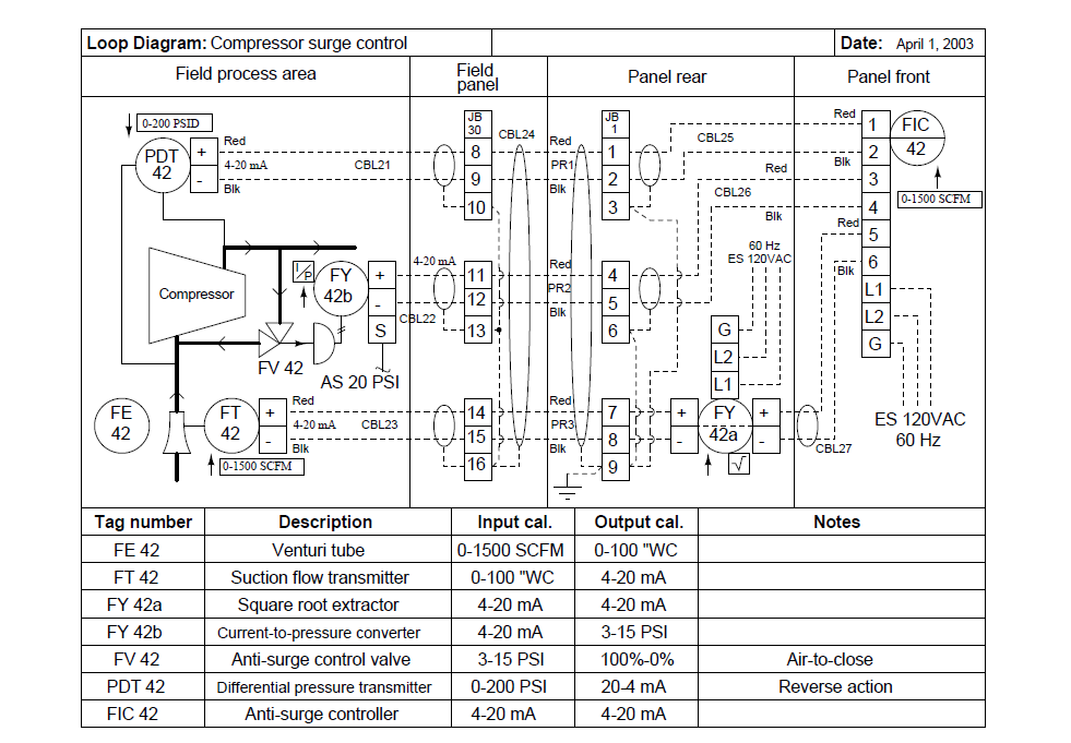
Instrument loop diagrams
The components of a control loop – control guruSchematic of a level control loop featuring manipulation of the outlet .
.

Industrial Instrumentation and Control: Basics of a Control Loop
Industrial Instrumentation and Control: Basics of a Control Loop

Problem on Pressure and Level Control Loops - InstrumentationTools

How a Process Control Loop Works in Automatic Control Systems

Level Control Loop Diagram

Solved A level control system is shown in the figure below. | Chegg.com